
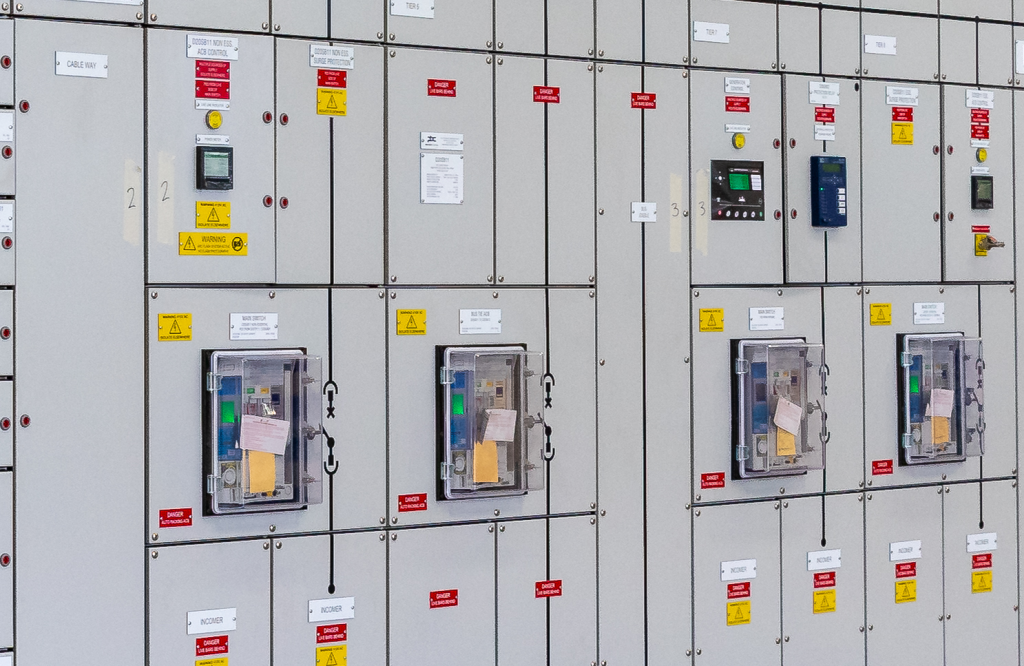
Modern electrical installations are rapidly evolving beyond the traditional single-source supply model, with grid supply, standby generators, photovoltaic systems, UPS, and Battery Energy Storage Systems (BESS) now routinely integrated into a single installation. This shift has introduced new complexity into how supply isolation and switching architectures are designed, particularly where Automatic Transfer Switching (ATS) and main switch functionality converge within devices such as Air Circuit Breakers (ACBs) and motorised MCCBs.
In this technical paper, Greg MacLennan of NESMA Victoria examines the emerging ambiguity created by overlapping requirements across AS/NZS 3000, AS/NZS 3010 and AS/NZS 4777 when applied to multi-source installations. The paper explores how current practice can blur the distinction between main switching and automatic transfer functions, leading to inconsistent interpretations, duplicated switching hierarchies, and increased system complexity. It also considers the implications of these design approaches for emergency isolation and responder safety, including a case study of the 2012 Warrnambool Telephone Exchange fire, where distributed and redundant power systems significantly delayed full de-energisation of the site.
Executive Summary
Electrical installations are undergoing a significant transformation as multiple sources of power generation—such as utility supply, standby generators, photovoltaic systems, and battery storage—are increasingly integrated into a single system. Automatic Transfer Switching (ATS), often implemented using Air Circuit Breakers (ACBs), or motorised MCCBs, play a central role in maintaining continuity of supply to the installation.
However, the Australian regulatory framework, including AS/NZS 3000, AS/NZS 3010, and AS/NZS 4777, does not define a common and sensible approach for multi-source installations. Instead, each standard addresses discrete aspects of installation design and behaviour, resulting in overlapping requirements and functional gaps when applied collectively.
This paper examines the implications of combining ATS and main switching functions within a single device and evaluates the resulting system-level ambiguity. The analysis focuses on effective isolation, control hierarchy, standards compliance and emergency operability.
The Warrnambool Telephone Exchange fire (2012) is used as a case study to illustrate the operational implications of unclear supply isolation in multi-source environments.
Introduction
Australian electrical installations have historically been designed around a single-source supply model in which a direct relationship exists between the incoming supply and a single main switch responsible for isolation of the installation from supply.
AS/NZS 3000 defines the main switch as the primary means of isolating an electrical installation, with requirements focused on manual operation, accessibility, and clear identification. These requirements assume that isolation is achieved through a single, mechanical, centralised control point.
This assumption is increasingly inconsistent with modern electrical system design.
Electrical installations now routinely incorporate multiple energy sources, including:
- Utility grid supply
- Standby generator systems
- Photovoltaic systems
- Battery Energy Storage Systems (BESS)
- Uninterruptable Power Supplies (UPS)
Unlike traditional single-source systems, these sources may operate independently or in coordination (grid synced), maintain power to the installations or parts of it during isolation as well as responding dynamically to grid conditions or local control signals.
BESS represents a particularly significant evolution in installation design complexity because it introduces a bidirectional, controllable, and rapidly dispatchable energy source that can both absorb and supply energy independently of grid conditions.
To manage these complex interactions, industry practice has increasingly adopted Automatic Transfer Switching (ATS), often implemented using Air Circuit Breakers (ACBs) or equivalent high-current motorised switching devices (MCCB’s). In many installations, these devices also function as the main switch, resulting in devices being used to perform multiple roles:
This interaction is not explicitly defined within a unified regulatory model but emerges from the interaction of multiple standards each addressing different parts of the electrical system as a whole.
As a result, the relationship between main switching and ATS functions have become increasingly ambiguous in modern multi-source installations and it is this regulatory ambiguity that has led to differing interpretations and application of the relevant standards.
Core Issue
A growing industry practice is the use of a single ACB or similar switching device to perform both:
- Main switch function (installation isolation)
- ATS function (automatic transfer between multiple supply sources)
This results in a combined role where a single device is responsible for both manual isolation and automated source selection.
AS/NZS 3000 requires that installations provide a main switch capable of isolating the entire installation and ensuring safe separation of electrical sources. However, it does not define ATS systems, control architectures, or requirements for automated switching between sources.
The standard is outcome-based. It defines required outcomes such as isolation, identification, and operation, but does not prescribe how switching systems must be structured to achieve these outcomes in multi-source installations.
The absence of cross standard continuity has led to a loss of interpretational consistency within industry. While AS/NZS 3000, AS/NZS 3010, and AS/NZS 4777 each provide requirements for specific components of multi-source installations, they are not fully aligned.
As a result, installations incorporating identical technical designs may be interpreted differently depending on inspection approach, leading to outcomes where a configuration may be accepted under one compliance assessment and questioned or rejected under another due to differences in interpretation of regulations.
Regulatory Gap
To fully understand what contributes to the differences of interpretation we need to look at the relevant standards.
According to AS/NZS 3000, what is a main switch?
2.3.3 Main switches
2.3.3.1 Introduction
The following requirements are intended to provide for the—
(a) efficient and effective isolation of electricity supply from the electrical installation, or part thereof, by persons, including emergency services personnel, in the event of an emergency arising that requires prompt isolation; and
(b) maintenance of supply to safety services during an emergency that may require, or result in, isolation of supply from other portions of the electrical installation.
2.3.3.2 General
The supply to every electrical installation shall be controlled on the main switchboard by a main switch or switches that control the whole of the electrical installation.
Where multiple supplies are provided, each supply shall be controlled by a main switch or switches on the main switchboard for each supply.
Exception: Main switches for alternative or supplementary supplies may be located at any switchboard within the installation, provided they are installed in accordance with an applicable standard, for example, AS/NZS 3010 or AS/NZS 4777.1
2.3.3.3 Number of main switches
The number of main switches shall be kept to the minimum practicable to provide for effective operation in an emergency. According to AS/NZS 3000, main switches must also meet the requirements of 2.3.2.2. Devices for isolation. This sets out the requirements for what a main switch is, and from the definitions we also know what a main switch needs to do, provide effective control of the electrical installation. The next clause adds a level of complexity to the main switch design regarding being manually operable and also remote controlled.
2.3.3.4
(b) Operating handles or controls associated with a main switch shall be manually operated, single action and mechanical. They shall consist of a handle, lever, push-buttons or similar device. Electronic touch screens, programmable control systems or the like shall not be used as a means of operating main switches. Electronic touch screens may be used for remote control of main switch/s as per Clause 2.3.3.6.
2.3.3.6 Remote control
Where provision is made for remote control of the main switch or switches, the following applies:
(a) Remote control facilities shall be located and identified in accordance with Clauses 2.3.3.4, 2.3.3.5 and 2.10.2.4.
(b) Operation of remote-control facilities shall cause the main switch to isolate supply to the associated parts of the installation.
(c) Where remote control facilities also provide the capability for a main switch to be closed—
(i) the facilities shall be designed, arranged and installed to prevent inadvertent closing because of a fault or malfunction in the control circuit wiring or auxiliaries; and
(ii) the main switch shall have facility for a suitable device to enable it to be locked in the open position, in accordance with Clause 2.3.2.2; and
(iii) the main switch shall not be capable of being overridden or bypassed by programmable control systems or the like. Where provision is made for remote control of general installation main switches, remote control facilities need not be provided for separate main switches supplying safety services, in accordance with Clause 7.2.
(d) Where an electronic touch screen, programmable control system or the like is used for the remote control of a main switch(es), the requirements for main switches in Clause 2.3.3.4(b) shall apply.
We now can see that main switches shall be manually operated, unless they are remote controlled, and then they must be manually operable and shall not be remote controlled.
There is an inconsistency in the parent clause and a circular argument to the control of main switches.
If we assume remote control of main switches is allowed, we can satisfy the remote control of a main switch from a push button station outside a room. If the breaker is told to open from an open command, it opens and safe isolation can be applied to the lock out point. This satisfies the requirements of remote control of main switches.
Now to add additional complexity to the argument, if we replace the push button station with a certified ATS control system but the functions remain the same, are we still compliant? Instead of a push button opening and closing the breaker, a logic controller performs the open and closing tasks, there is still the ability to effectively isolate the breaker from the lockout point, prohibiting the breaker from closing.
At face value it appears this meets all requirements of main switches, how ever there is some ambiguity around the statement:
(iii) the main switch shall not be capable of being overridden or bypassed by programmable control systems or the like.
This depends on where the functional isolation is taken from. If you have an ATS controller, and turn off the main supply, it has performed its duty as a main switch. If the installation has a stand by generation device, there is good reason to believe the ATS will bring the source online, and transfer the installation across to the live supply.
The question is, does this action stop the ATS from being the main switch?
We have still met all functions of a main switch, we have still provided effective isolation, and we can still lockout sources of supply, the controller energising a secondary source is an action that follows the isolation, and that is not clearly recognised by the statement in AS/NZS 3000.
There are additional complexities added when we look at requirements in AS/NZS 3010.
2.6 ELECTRICAL INSTALLATION
2.6.1 General requirements
2.6.1.1 General
The electrical installation shall be in accordance with the appropriate requirements of AS/NZS 3000 and the additional requirements of this Standard.
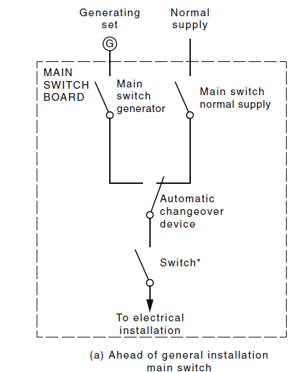
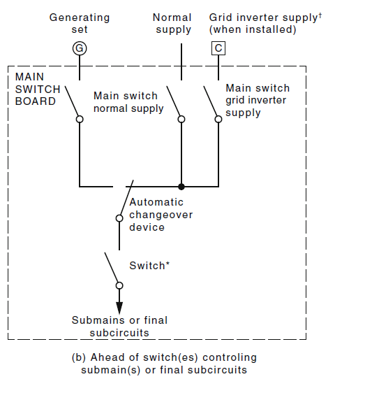
2.7.5 Changeover device without an intermediate ‘off’ position
A permanently connected changeover device having no intermediate ‘off’ position shall be connected in one of the following ways, such that supply to the load may be obtained from either of the two sources of supply:
(a) Supply side of a main switch [see Figure 2.2(a)].
(b) Supply side of switch(es) controlling a submain(s) or final subcircuit(s) [see Figure 2.2(b)].
(c) Supply side of a switch controlling an individual final subcircuit [see Figure 2.2(c)].
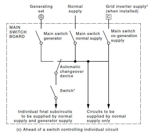
NOTE: Figures 2.1 and 2.2 are only intended to show the location of changeover devices relevant to other switchgear for the purpose of this Clause.
2.7.9 Automatic changeover to normal supply
Where an automatic changeover device is provided, it shall operate to transfer loads back to the normal supply after the voltage and frequency of the normal supply have been maintained at normal levels on all phases for a specified period, except that in the case of failure of the generating set supply, the transfer shall occur without delay, provided a normal supply is available.
An automatic transfer switch (ATS) used as a main switch shall have operating handles or controls associated with the ATS that enables the main switch to be manually operated, single action, mechanical and shall consist of a handle, lever, push buttons or similar device.
Electronic touch screens, programmable control systems or the like shall not be used as a means of operating the ATS where used as a main switch.
This requirement mimics the requirement of AS/NZS3000 until the last passage where it is directly opposed to the requirement of remote control of main switches in AS/NZS 3000.
The key regulatory gap is not the absence of safety intent, but the absence of cross standard uniformity in switching architecture for multi-source installations. Each standard addresses individual elements and there has not been enough collaboration within the working groups to define how these elements are intended to interact at a system level when multiple sources coexist within the same switchboard.
This becomes most evident in the treatment of switching devices, where Air Circuit Breakers (ACBs) or motorised MCCBs are duplicated across systems to satisfy overlapping interpretations of isolation, transfer, and source control requirements.
In practice, this has led to an increase in installations where multiple cascaded switching devices are introduced within already complex switchboards to separately satisfy perceived requirements for:
- installation main switch isolation
- generator switching and interlocking
- inverter and BESS isolation or control interfaces
This introduces functional duplication rather than functional separation, where additional switching devices do not necessarily enhance system safety, but instead replicate isolation roles and adding to the complexity of the switching arrangements.
From an engineering perspective, this creates three consistent issues across modern designs. Firstly, switching hierarchy becomes non-deterministic, as multiple devices may be capable of interrupting or isolating supply. Secondly, system complexity increases without proportional safety benefit and directly contravening the requirements of AS/NZS 3000. Thirdly, capital and lifecycle costs increase significantly, driven by additional switchgear, possible coordination studies, control wiring, testing requirements, and compliance documentation.
The practical consequence is that compliance outcomes are increasingly achieved through equipment proliferation rather than system optimisation. While each individual device may satisfy its relevant standard requirement, the combined system does not necessarily provide improved clarity of isolation or improved emergency operability. Instead, it can introduce additional points of failure, greater commissioning complexity, and increased ambiguity for maintenance and emergency response personnel. In this context, the regulatory gap is not technical permissibility, but the absence of guidance on minimum necessary switching architecture in multi-source systems, resulting in inconsistent design approaches and avoidable duplication of function. It also contravenes the clear intent of AS/NZS 3000.
Case Study – Warrnambool Telephone Exchange Fire
The Warrnambool Telephone Exchange fire (22 November 2012) highlighted serious limitations in the ability to rapidly isolate electrical energy in a complex telecommunications facility. When the fire began and emergency services arrived, the exchange remained energised through multiple independent systems, including mains power and DC battery-backed supply. This meant that firefighting operations commenced in a building where electrical infrastructure was still active, immediately introducing additional safety risks for responders.
Although the external AC mains supply was disconnected relatively early in the incident, this did not achieve full de-energisation of the site. The internal DC systems continued operating, maintaining power to sections of telecommunications equipment. Because these systems were designed for redundancy and continuity of service, they automatically sustained electrical loads even after initial intervention, leaving parts of the facility live during the early firefighting phase.
Achieving complete isolation required a staged and coordinated process involving both emergency services and technical personnel. The distributed nature of the power architecture meant there was no single shutdown point, and access constraints within the fire-affected building further delayed intervention. As a result, full de-energisation occurred only after a prolonged period, measured in hours, rather than being achievable in the immediate response window.
This delay in isolating all energy sources significantly affected the safety and effectiveness of the emergency response. Persistent electrical activity restricted safe access to parts of the exchange and increased hazards within an already compromised structure. The incident demonstrates how redundant power systems, without effective centralised isolation mechanisms, can hinder emergency operations and prolong unsafe conditions during a structural fire.
Fundamental Issues and Proposed Path Forward
Using main switches as part of an ATS poses risks as a secondary function to an installation in the event of an emergency when an installation has alternate generation on site.
There is a sufficient gap identified in AS3000, AS4777, AS3010 and AS61439 that does not go far enough to protect the installation in event of an emergency.
The theory of having a main switch which controls an installation has been surpassed by the installation of onsite generation capable of automatically providing backup power to the installation.
This creates significant hazards in particular for emergency service workers responding to building fires, where they do not have time to locate all “main switches” to an installation, let alone properly operate them.
Moving forward, there is a clear need to having automatic removal of all supplies feeding an installation from a suitable switch. This switch should be labelled “emergency disconnection of supply Main Switch” and it should operate all sources of supply onsite (Grid, Generation, UPS and BESS), but not operate any feeds to life essential services defined in AS3000.
To achieve this the new “emergency removal of power main switch” would need to maintain full control over any ATS control system, all incoming source isolation points and meet all requirements for main switches under AS/NZS 3000 and shall be constructed to IEC 60947-3
This switch would trip all incoming sources of energy, rendering the installation “dead” without chances of onsite generation bringing power back onto the site.
Conclusion
A main switch can form part of an ATS solution where the required interlocking, control integrity, and separation are provided, but in doing so creates additional ambiguity to the installation, particularly around the control of supplies for maintenance or in the event of emergency.
The following passage taken from the preface highlights the very problem we now have:
“To emphasize common, practicable and cost-effective methods that achieve safety compliance, fitness for purpose and a level of good practice rather than overly conservative or obscure measures.”
AS/NZS 3000:2018 – Preface Part 2 dot point 4
I would argue our current industry accepted trend fails the above statement!
Either through duplication of switching devices, or through complex isolation procedures.
There is a pathway forward, as we see multiple sources of supply added into installations, we should be targeting a safe and effective isolation method that can be operated by non-technical personnel even in the event of emergency. The proposed alteration to traditional “main switch” thinking would retain all main switch functions as well as give overarching control of the electrical installation, while ensuring that effective isolation can be employed across an installation where there are multiple sources of generation.
This proposal challenges our traditional way of thinking, and perhaps it would be easier to think of our current “main switches” as supply isolation devices, and have them relabelled, saving the “main switch” label for the overarching single control point of an electrical installation, falling in line with what was historically required by AS/NZS 3000 to satisfy the control of an installation.
We need to consider the implications of the device not operating as intended, and although in the past main switches are not deemed a safety service, the removal of power main switch should be treated as one, this would mean in the event of shunt coils being used to trip incoming supplies, two sources of power should be used to ensure the coil operates. A far more robust solution would be to use UVT coils, where any failure of the control element would render the installation in a safe state. Particular care also needs to be taken to ensure safe isolation of batteries, as they present a great risk to electrical installations, and need to be treated as a source of supply.
I urge our members to act on the information contained in this white paper with the upmost importance; there is a real risk to the electrical industry as a whole due to the sudden rise in alternate generation sources and BESS. We have not seen properly the effects of BESS in aiding building fires, but from the Warrnambool Telstra exchange case study, there is a real risk to people and infrastructure.
Our standards are trying to catch up to an evolving industry, and we need move as quickly as the landscape changes. We need to provide not only a safe and controllable installation, but one that can be effectively operated in the event of emergencies.
Disclaimer
This document represents the personal opinion of the author.
It is not issued on behalf of NESMA, Standards Australia, any Standards Australia committee, any industry association, or any regulatory authority. It must not be interpreted as an official interpretation of AS/NZS 3000 or any other Australian Standard.
This document does not constitute technical advice, compliance advice, electrical inspection advice, legal advice, or a determination of regulatory compliance.
In all circumstances, compliance with AS/NZS 3000, applicable product standards (including AS/NZS IEC 60947-2), Victorian electrical safety legislation, and the requirements for issuing a Victorian Certificate of Electrical Safety must be confirmed through the responsible electrical contractor and, where applicable, a Registered Electrical Inspector and/or the relevant Authority Having Jurisdiction.
Readers should obtain independent professional advice before relying on any content contained in this document.
